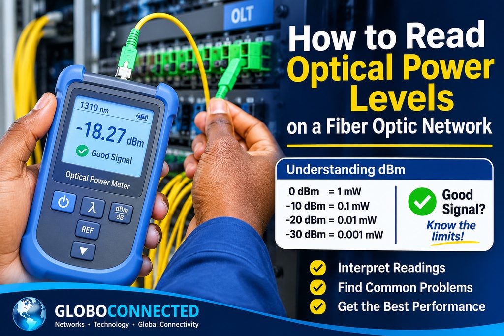
How to Read Optical Power Levels on a Fiber Optic Network
Optical power measurements are among the most useful indicators of fiber optic network health. Whether you are troubleshooting an FTTH connection, monitoring a GPON network, or testing a point-to-point fiber link, understanding optical power levels helps you determine whether a signal is reaching its destination within the equipment’s operating limits.
However, reading an optical power meter is not simply about checking whether a number is high or low. You also need to understand the measurement unit, the direction of the optical signal, the wavelength being tested, and the receiver’s specifications.
This guide explains how to interpret optical power readings, understand dBm values, identify potential signal problems, and perform basic measurements on fiber optic networks.
1. What Are Optical Power Levels?
Optical power refers to the amount of light energy transmitted through a fiber optic cable. In telecommunications networks, optical transmitters convert electrical signals into light, which travels through the fiber before reaching an optical receiver.
The received optical power determines whether the receiver has sufficient signal strength to detect and process the transmitted information.
Optical power is commonly measured in dBm (decibels referenced to one milliwatt).
A fiber optic power meter displays the amount of optical power reaching its detector. For example, a reading of -18 dBm indicates a different optical power level from -28 dBm.
Understanding this difference is essential when diagnosing signal degradation, excessive attenuation, or unstable fiber connections.
2. Understanding dBm and dB in Fiber Optics
One of the most common mistakes in fiber optic testing is confusing dBm with dB. Although both units are used in optical measurements, they represent different things.
What Does dBm Mean?
dBm is an absolute measurement of optical power referenced to 1 milliwatt (mW).
Some useful reference values include:
| Optical power | Equivalent power |
|---|---|
| 0 dBm | 1 mW |
| -10 dBm | 0.1 mW |
| -20 dBm | 0.01 mW |
| -30 dBm | 0.001 mW |
A negative dBm reading does not automatically indicate a faulty connection. Fiber optic communication systems commonly operate with negative optical power levels.
What Does dB Mean?
dB measures the difference or ratio between two power levels. In fiber optic networks, it is commonly used to express attenuation, insertion loss, and optical power differences.
For example, if a fiber link receives -15 dBm at one point and -20 dBm at another, the difference is 5 dB.
This represents a reduction in optical power along the measured path.
The important distinction: Use dBm to describe the absolute optical power measured at a point, and dB to describe the difference between two power levels.
3. How to Read an Optical Power Meter
A fiber optic power meter is the primary instrument used to measure optical power at the end of a fiber connection.
Most handheld optical power meters display the measured value in dBm or microwatts, depending on the selected measurement mode.
To obtain a meaningful reading, follow these steps:
- Inspect and clean the fiber optic connector and the power meter adapter.
- Connect the fiber to the optical power meter using a compatible adapter.
- Select the correct wavelength for the optical signal being measured.
- Select dBm as the measurement unit.
- Ensure that the optical source is active.
- Allow the reading to stabilize and record the measured value.
For common single-mode telecommunications systems, 1310 nm and 1550 nm are important test wavelengths. GPON systems also use 1490 nm for downstream transmission and 1310 nm for upstream transmission.
The selected wavelength must correspond to the signal being measured.
It is also important to remember that optical connectors should be inspected and cleaned before testing. Contamination can introduce additional loss and produce misleading measurements.
4. How to Interpret Optical Power Readings
The interpretation of an optical power reading depends on the equipment, optical technology, receiver sensitivity, and maximum input power.
A stronger optical signal is not necessarily always better. If the received power exceeds the receiver’s maximum input specification, the receiver may experience overload.
Likewise, if the received power falls below its sensitivity threshold, communication may become unstable or stop completely.
Consider the following illustrative readings:
| Measured power | General interpretation |
|---|---|
| -10 dBm | Relatively strong optical signal |
| -15 dBm | Stronger than -20 dBm |
| -20 dBm | Lower optical power |
| -25 dBm | Weaker optical signal |
| -30 dBm | Very low optical power in many applications |
These values are examples for understanding relative signal strength, not universal pass/fail thresholds.
Always compare the measured value with the transmitter and receiver specifications for the equipment being tested.
Example: Comparing Two Optical Readings
Suppose an ONT reports an optical receive power of -18 dBm, while another ONT on the same type of network reports -25 dBm.
The difference is 7 dB.
The first ONT receives considerably more optical power than the second. However, this does not automatically mean the second connection is faulty.
Differences in fiber length, splitter configuration, connectors, splices, and optical distribution paths can explain variations in received power.
The correct approach is to compare each reading against the designed optical budget and the equipment’s operating limits.
5. Understanding Optical Power in GPON Networks
In a GPON network, optical power is particularly important because multiple subscribers share an optical distribution network through passive splitters.
The OLT transmits downstream optical signals toward ONTs, while ONTs transmit upstream signals toward the OLT.
This creates two important measurement directions:
- Downstream: Optical power received by the ONT from the OLT.
- Upstream: Optical power received by the OLT from the ONT.
A technician should understand which direction is being measured before interpreting an optical power value.
For example, an ONT’s received optical power provides information about the downstream signal reaching the subscriber’s premises.
GPON optical budgets also depend on the optical class of the equipment. ITU-T G.984.2 defines physical-layer specifications, including transmitter and receiver characteristics.
For GPON B+ equipment, the receiver sensitivity and overload limits are important reference points. These are commonly specified around -28 dBm and -8 dBm respectively, subject to the applicable equipment specification and measurement conditions.
This means that a reading should never be judged independently of the optical interface specifications.
6. Common Causes of Low Optical Power
When an optical power reading is lower than expected, several physical and network-related problems may be responsible.
Dirty Fiber Optic Connectors
Dust, oil, and other contaminants on connector end faces can introduce significant optical loss.
Inspecting and cleaning connectors is one of the first steps in troubleshooting.
Excessive Fiber Bending
Fiber optic cables have minimum bend-radius requirements. Excessive bending can introduce additional attenuation and affect signal transmission.
Poor Fusion Splices
Improper fusion splicing can introduce additional insertion loss. Damaged fiber ends, poor alignment, and inadequate preparation may contribute to the problem.
Damaged Fiber Cables
Physical damage caused by construction work, accidental cuts, crushing, or environmental conditions can interrupt or degrade optical transmission.
Excessive Splitter Loss
In GPON networks, optical splitters distribute the signal among multiple subscribers.
Higher splitting ratios introduce greater insertion loss. For example, a 1:32 splitter generally introduces more splitting loss than a 1:8 splitter.
The complete optical path must therefore be considered when evaluating received power.
7. Optical Power Meter vs. OTDR: Which Tool Should You Use?
An optical power meter and an Optical Time Domain Reflectometer (OTDR) serve different purposes in fiber optic troubleshooting.
An optical power meter measures the optical power reaching its detector at a particular point.
An OTDR sends optical pulses into a fiber and analyzes the returned light to identify events along the link, including connectors, splices, bends, and possible fiber breaks.
Use an optical power meter when you need to:
- Check the optical power received by an ONT.
- Measure transmitter output power.
- Verify the power available at a fiber endpoint.
- Investigate whether a link has sufficient received optical power.
Use an OTDR when you need to:
- Locate a fiber break.
- Identify high-loss splice points.
- Investigate unexpected attenuation along a fiber route.
- Estimate the distance to a fault.
These instruments complement each other. A power meter helps establish the optical power available at a measurement point, while an OTDR helps investigate where events and losses occur along the fiber.
8. Best Practices for Accurate Optical Power Measurements
Accurate optical measurements require proper equipment handling and consistent testing procedures.
Consider the following practices:
- Clean connectors before connecting test equipment.
- Use compatible adapters and test cables.
- Select the correct wavelength.
- Verify that the optical power meter is calibrated.
- Avoid unnecessary fiber bending during testing.
- Record the measurement location and direction.
- Compare readings with the equipment’s optical specifications.
- Use an OTDR when additional investigation of the fiber path is required.
Safety note: Never look directly into a fiber optic connector or transmitter port. Invisible laser radiation can cause eye injury even when no light is visible.
Conclusion
Understanding how to read optical power levels is an essential skill for fiber optic technicians, NOC engineers, and network administrators.
By understanding the difference between dBm and dB, selecting the correct wavelength, interpreting receiver power levels, and using appropriate testing equipment, technicians can identify potential optical problems more effectively.
However, no single optical power value can determine the health of every fiber connection. Reliable troubleshooting requires comparing measurements against the equipment specifications, the designed optical budget, and the physical condition of the fiber infrastructure.
A properly interpreted optical power reading is not just a number on a meter. It is an important diagnostic indicator of fiber network performance.
Pingback: Single-Mode vs Multimode Fiber: Which One Should You Use? - Globo Connected