Spanning Tree Protocol Explained: How STP Prevents Network Loops
Redundant links keep a switched network alive when a cable or a switch fails. However, those same links can bring the whole network down in seconds if nothing controls them. The spanning tree protocol solves this problem by blocking extra paths until they are needed. In this guide, we explain how the spanning tree protocol works, how it chooses its paths, and how to configure and protect it on real switches.
What Is Spanning Tree Protocol?
The spanning tree protocol (STP) is a Layer 2 protocol that builds a loop-free logical topology on a switched Ethernet network. Switches exchange small messages called bridge protocol data units (BPDUs), elect one switch as the root, and then block every path that would create a loop. As a result, the physical network can contain many redundant links, while the logical network behaves like a tree with exactly one active path between any two points.
A simple analogy helps here. Picture a city with several roads between two districts. If every road stays open and drivers circle endlessly, traffic never clears. Instead, the city keeps one main road open and closes the others, then reopens a closed road if the main one is blocked. In the same way, STP keeps backup links in reserve and activates them only after a failure.
Why Layer 2 Loops Are Dangerous
Unlike IP packets, Ethernet frames have no time-to-live (TTL) field. Therefore, a looped broadcast frame never expires. Switches keep copying it out of every port, and the frame multiplies with each pass. Three problems follow almost immediately:
- Broadcast storms. Looping frames consume all available bandwidth, so normal traffic cannot get through.
- MAC table instability. The same source address appears on different ports again and again, which is known as MAC flapping.
- High CPU usage. Switches and end devices spend their resources processing duplicate frames, and many devices become unreachable.
A common real-world scenario shows how fast this happens. Someone plugs both ends of a patch cable into the same small desk switch, or connects a second switch to a wall port that already leads to the main network. Within seconds, the entire VLAN slows to a crawl. Consequently, without STP, one careless cable can take down a whole floor.
How the Spanning Tree Protocol Elects a Root Bridge
Every STP decision starts with the root bridge. All switches in the network agree on one switch with the lowest Bridge ID, and every other switch then calculates its best path toward it.
Understanding the Bridge ID
The Bridge ID combines a priority value with the switch MAC address. On modern Cisco switches running per-VLAN versions of STP, the priority field also carries the VLAN number as an extension. The default priority is 32768, and you can change it only in steps of 4096. The switch with the lowest Bridge ID wins, and if priorities match, the lowest MAC address breaks the tie.
This detail matters in practice. Because every switch uses the same default priority, the switch with the lowest MAC address often becomes the root, and that is frequently the oldest and weakest switch in the building. Therefore, you should always choose the root bridge yourself instead of leaving the decision to chance.
Root Path Cost
After the election, each non-root switch adds up the link costs along each path to the root. Faster links have lower costs, so the best path is usually the fastest one. The table below shows the two common cost schemes.
| Link speed | Short (classic) cost | Long (newer) cost |
|---|---|---|
| 10 Mbps | 100 | 2,000,000 |
| 100 Mbps | 19 | 200,000 |
| 1 Gbps | 4 | 20,000 |
| 10 Gbps | 2 | 2,000 |
Note that all switches in the same domain should use the same cost method. Otherwise, path calculations can produce unexpected results.
Spanning Tree Protocol Port Roles
Once the root bridge is known, each switch assigns a role to every port:
- Root port. On each non-root switch, this is the port with the lowest total cost to the root. If two ports tie, STP compares the sender’s Bridge ID and then the sender’s port ID.
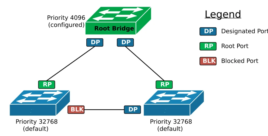
- Designated port. Each network segment has exactly one designated port, which forwards traffic toward that segment. All ports on the root bridge are designated.
- Non-designated port. Any port that is neither root nor designated is blocked. This is how STP breaks the loop.
A Worked Example
Imagine three switches connected in a triangle with 1 Gbps links, so each link has a cost of 4. SW1 has the lowest Bridge ID and becomes the root.
- SW2 and SW3 each choose the direct link to SW1 as their root port, because the cost is 4.
- On the SW2-to-SW3 link, both switches advertise the same root path cost of 4. As a result, the lower Bridge ID wins the designated role. Say that is SW2.
- Finally, SW3’s port on that link becomes non-designated and blocks traffic.
The loop is gone. Moreover, if the SW3-to-SW1 link fails, SW3’s blocked port moves toward forwarding, and traffic reaches the root through SW2.
Spanning Tree Protocol Port States
In classic STP (IEEE 802.1D), a port moves through several states before it forwards traffic. This delay protects the network from temporary loops while the topology settles.
| State | Receives BPDUs | Learns MAC addresses | Forwards user frames |
|---|---|---|---|
| Blocking | Yes | No | No |
| Listening | Yes | No | No |
| Learning | Yes | Yes | No |
| Forwarding | Yes | Yes | Yes |
| Disabled | No | No | No |
In short, a port first listens, then learns, and only then forwards. That careful progression is safe, but it is also slow, which explains why newer versions of the protocol exist.
STP Timers and Convergence Time
Classic STP relies on three timers:
- Hello timer: 2 seconds. The root sends a BPDU every hello interval.
- Forward delay: 15 seconds. This is the time spent in both the listening and learning states.
- Max age: 20 seconds. This is how long a switch keeps the last BPDU before it declares the path lost.
Because of these timers, convergence is slow. After a direct link failure, a blocked port needs about 30 seconds to reach forwarding. After an indirect failure, the switch must first wait for max age to expire, so recovery can take up to 50 seconds. For modern applications, that delay is far too long.
When the topology changes, switches also send topology change notifications (TCNs) toward the root. The root then signals the change to the rest of the network, and switches shorten their MAC table aging time so that stale entries disappear quickly. Frequent topology changes therefore cause extra flooding, and they are worth investigating.
Spanning Tree Protocol Variants: STP, PVST+, RSTP and MST
Over the years, several versions of the spanning tree protocol have appeared. Each one improves speed or scalability.
| Version | Standard | Trees | Convergence | Notes |
|---|---|---|---|---|
| STP | 802.1D | One for all VLANs | 30 to 50 seconds | Simple, but slow |
| PVST+ | Cisco | One per VLAN | 30 to 50 seconds | Allows per-VLAN load balancing |
| RSTP | 802.1w | One for all VLANs | Typically a few seconds or less | Fast, backward compatible |
| Rapid PVST+ | Cisco | One per VLAN | Typically a few seconds or less | RSTP applied per VLAN |
| MST | 802.1s | Few, mapped to VLAN groups | Typically a few seconds or less | Scales to many VLANs |
Rapid Spanning Tree Protocol (RSTP)
RSTP keeps the same basic idea but reacts much faster. Instead of waiting for timers, neighboring switches negotiate directly using a proposal and agreement handshake on point-to-point links. Meanwhile, RSTP simplifies the port states to three: discarding, learning, and forwarding.
It also adds two port roles. An alternate port is a ready-made backup path to the root, so failover is almost immediate. A backup port is a redundant connection to the same segment. In addition, edge ports, which connect to end devices, move straight to forwarding. Finally, each switch treats three missed BPDUs as a link failure, so detection is far quicker than in classic STP.
Multiple Spanning Tree Protocol (MST)
When a network has hundreds of VLANs, running one tree per VLAN wastes switch resources. MST solves this by mapping groups of VLANs to a small number of instances. For example, VLANs 10 to 50 can follow instance 1, while VLANs 60 to 100 follow instance 2. However, all switches in an MST region must share the same region name, revision number, and VLAN-to-instance mapping. If one switch differs, it falls outside the region.
Spanning Tree Protocol Configuration Example
Consider a small design with two distribution switches (SW1 and SW2) and one access switch (SW3). The network carries VLAN 10 and VLAN 20. The goal is to make SW1 the root for VLAN 10 and SW2 the root for VLAN 20, so both uplinks carry traffic and each switch backs up the other.
! SW1
spanning-tree mode rapid-pvst
spanning-tree vlan 10 priority 4096
spanning-tree vlan 20 priority 8192

! SW2
spanning-tree mode rapid-pvst
spanning-tree vlan 20 priority 4096
spanning-tree vlan 10 priority 8192

! SW3
spanning-tree mode rapid-pvst
Remember that priorities must be multiples of 4096. Alternatively, the commands spanning-tree vlan 10 root primary and spanning-tree vlan 10 root secondary set suitable values automatically. To verify the result, use these commands:
show spanning-tree summary
show spanning-tree root
show spanning-tree vlan 10
show spanning-tree interface gigabitethernet0/1 detail
For an MST design, the configuration looks different:
spanning-tree mode mst
spanning-tree mst configuration
 name CAMPUS
 revision 1
 instance 1 vlan 10-50
 instance 2 vlan 60-100
Protecting the Network: PortFast, BPDU Guard, Root Guard and Loop Guard
A correct design is only half the job. Users can still plug in rogue switches, and cables can still fail in strange ways. Fortunately, a few features add strong protection:
- PortFast moves access ports straight to forwarding, so PCs and phones get connectivity quickly.
- BPDU Guard shuts a port down (err-disable) if it receives a BPDU. Use it together with PortFast, because an access port should never receive one.
- Root Guard stops a port from accepting a better root. If a superior BPDU arrives, the port enters a root-inconsistent state until it stops.
- Loop Guard prevents a blocked port from forwarding if it suddenly stops receiving BPDUs, which protects against one-way link failures.
interface range gigabitethernet0/1 - 24
 spanning-tree portfast
 spanning-tree bpduguard enable

interface gigabitethernet0/48
 spanning-tree guard root

interface gigabitethernet0/47
 spanning-tree guard loop
Troubleshooting Spanning Tree Protocol Problems
When something goes wrong, start by identifying the root bridge with show spanning-tree root. Then check the symptom against this table.
| Symptom | Likely cause | What to check |
|---|---|---|
| Wrong switch is the root | New switch with a lower MAC or priority joined the network | Set explicit priorities and add Root Guard |
| Frequent topology changes | A flapping link or a host port without PortFast | Run show spanning-tree detail and find the interface that sent the last change |
| Port in err-disabled state | BPDU Guard triggered by a rogue switch | Remove the device, then recover the port |
| Port in root-inconsistent state | Root Guard received a superior BPDU | Find the switch sending it |
| Broadcast storm | A loop from a rogue switch, a disabled STP, or a one-way link | Check interface utilization and shut down suspect ports |
During a storm, speed matters. First, look for ports with unusually high traffic counters. Next, shut them down one at a time until the storm stops. Afterward, find the cause and fix it before you re-enable anything.
Best Practices for a Stable Layer 2 Network
- Choose your root bridge. Set a primary and a secondary root, and place them in the core or distribution layer.
- Use a fast version. Prefer Rapid PVST+ or MST over classic STP.
- Protect access ports. Enable PortFast and BPDU Guard on every port that faces an end device.
- Guard the edges. Apply Root Guard on ports that should never lead to the root.
- Bundle parallel links. EtherChannel treats several links as one logical link, so STP does not block them.
- Keep Layer 2 small. Smaller VLAN domains mean fewer loops and faster recovery.
- Never disable STP casually. Even in modern designs, it remains an important safety net.
- Document everything. A clear diagram of root bridges and blocked ports saves time during outages.
Modern designs such as routed access and leaf-spine fabrics reduce reliance on STP. Nevertheless, most campus and office networks still depend on it every day.
Final Thoughts on Spanning Tree Protocol
In short, the spanning tree protocol keeps redundant networks safe by electing a root bridge, assigning port roles, and blocking the links that would form loops. Rapid versions react in seconds, and protection features guard against human error. Therefore, start by choosing your root bridge deliberately, then enable Rapid PVST+ or MST, and finally add PortFast, BPDU Guard, and Root Guard to every edge. With those steps in place, the spanning tree protocol will quietly protect your network, and your users will never notice it working.
Pingback: Network Address Translation Explained: How NAT Works - Globo Connected